This article mainly focuses on how to select suitable flow meters for non-shutdown and non-flow-interruption pipeline installation in industrial production scenarios.
In industrial production processes, flow measurement is a critical parameter ensuring operational stability. Most flow meters require pipeline shutdown and cutting during installation. However, certain key pipelines need year-round operation, necessitating the selection of flow meters suitable for non-shutdown and non-flow-interruption installation.
Based on different media types, application scenarios, and customer-specific requirements, various inline-installable flow meters are available.
Insertion Installation: A Common Approach
Insertion installation is one of the most widely used methods. By drilling a hole in the pipeline and inserting the sensor, it is compatible with multiple flow meter types, including electromagnetic, ultrasonic, vortex shedding, and pitot tube/differential pressure (DP) flow meters.
Pre-installation Preparation: Use specialized drilling tools to ensure operations are performed under pressure, preventing medium leakage.
Installation Notes: Strictly follow requirements for sensor insertion depth and orientation to guarantee measurement accuracy.
Application Scenarios of Different Flow Meters
1. Insertion Electromagnetic Flow Meter
Accuracy: ±2.0%
Applicable Media: Single conductive media
Maximum Temperature Resistance: 70°C
Advantages: No pressure loss, corrosion resistance
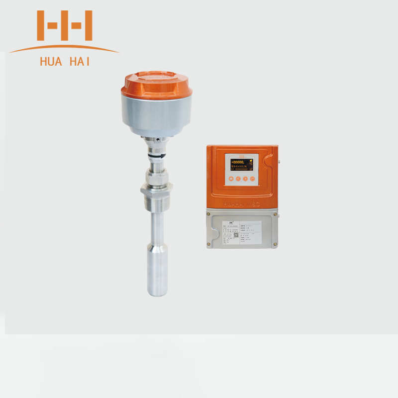 Insertion Electromagnetic Flow Meter
2. Ultrasonic Flow Meter
Key Application: Ideal for large-diameter pipelines and systems where shutdown is impractical. Clamp-on ultrasonic flow meters enable non-contact measurement without pipeline drilling.
Performance Parameters:
Accuracy: ±1.5%
Maximum Temperature Resistance: 110°C
Measurable Media: Uniform, single-phase stable liquids (e.g., water, seawater, industrial wastewater, alcohol, acid-base solutions, various oils)
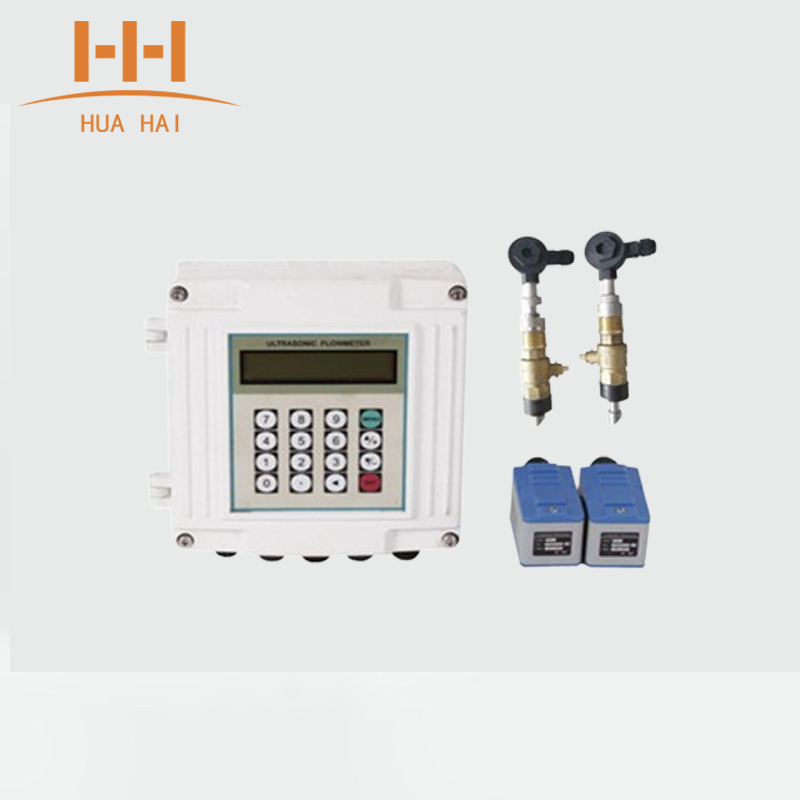 Ultrasonic Flow Meter
3.Insertion VortexFlow Meter
Applicable Media: Gases, steam, and low-viscosity liquids
Advantages: Simple structure, wide media compatibility
Limitations: Sensitive to vibration
Performance Parameters:
Measurable Media: Liquids, gases, steam
Nominal Diameter: DN200–DN3000 (custom non-standard products available)
Temperature Range: -40°C ~ 250°C
4.Insertion Thermal Mass Flow Meter
Key Features: No temperature/pressure compensation required for gas measurement; direct and accurate mass flow or standard volumetric flow output
Advantages: Wide turndown ratio (measurable velocity: 0.1–100 Nm/s), suitable for gas leak detection
Maximum Diameter: Up to DN3000
Insertion Thermal Mass Flow Meter
5.Pitot Tube/Differential Pressure (DP) Flow Meter
Category: Insertion-type DP flow meter
Advantages: Inherits the wide media compatibility of traditional DP flow meters; suitable for full-pipe flowing media (gases, liquids, steam); high temperature/pressure resistance
Measurement Lower Limit: Determined by the minimum differential pressure requirement
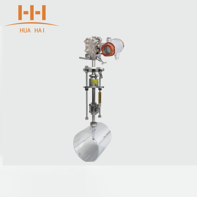
Differential Pressure (DP) Flow Meter
Installation Procedures for Inline Flow Meters
1.Select a proper installation location directly above or below the target pipeline. Weld the base and install a valve.
2.Mount the specialized drilling tool on the ball valve and ensure tight sealing.
3.Perform drilling, retract the drill bit, close the valve, and remove the drilling tool.
4. Install the flow meter, open the ball valve, adjust the orientation, fasten the unit, and verify sealing.
Accuracy Assurance & Calibration Strategies
1.Conduct zero calibration and range setting before installation to establish a baseline for accuracy.
2.For insertion and clamp-on flow meters, accurately input pipeline parameters (outer diameter, wall thickness, material, etc.), as these directly impact measurement precision.
3.Periodic Verification:
Flow meters for trade settlement: Calibrate every 6 months.
Flow meters for process control: Calibrate every 1–2 years.
4.Use portable ultrasonic flow meters for comparison, especially suitable for large-diameter pipelines.
5. Critical for gas and steam measurement. Select appropriate compensation formulas based on medium properties, distinguishing between saturated and superheated steam.
6.Signal Processing Optimization: Set a reasonable damping time (typically 3–5 seconds) to balance response speed and stability, reducing fluctuations.
7.Electromagnetic Interference (EMI) Suppression: Use shielded cables and single-point grounding (ground resistance ≤1Ω) in interference-prone environments.
 Insertion Electromagnetic Flow Meter
 Ultrasonic Flow Meter


