Product overview
The intelligent digital regulator produced by our company adopts the special integrated circuit developed by ourselves and commissioned by Japanese integrated circuit manufacturers. It not only integrates most functions of various regulating instruments in the current automatic control system, but also integrates circuits such as CPU, I / O interface, EPROM and D / a conversion, supplemented by a software system that is well-designed and repeatedly debugged by taking advantage of all advantages This instrument has the following characteristics:
1. The instrument hardware is greatly reduced, and the system structure is relatively simple. A variety of input signals are compatible within the scope of user application.
2. The optimized design is adopted, the process is significantly improved, there is no flying wire, no potentiometer adjustment, all the calibration and functions can be completed by the software through the keyboard.
3. Up to six alarm outputs can be set, and more than ten alarm methods can be used, and the alarm parameters can be monitored.
4. Two D / A output ports can be added to ensure the safety and reliability of the controlled system. Two constant voltage sources, 5V and 24V, are provided to meet the requirements of most auxiliary functions.
5. Any complex control, adjustment, alarm, output and other functions can be operated simply by the instrument operator, and password protection can be applied after setting to make it become a fool instrument. The field operator will not be able to modify the locked parameters. It can even prevent operators from checking. There are four categories and hundreds of levels of anti-jamming modes set by the user, which can adapt to the interference sources of various environments.
6. Linear input or pt100x instrument can customize zero point and full degree.
Product selection
|
Spectrum
|
Illustration
|
|
Type
|
XMTA |
Smart digital display regulation transmitter
|
| XMGA |
Smart streamer display regulation transmitter
|
| 1 |
1000 Series digital display instruments
|
| 2 |
2000 Series streamer instruments
|
|
Indication
|
1 |
Single screen display
|
| 2 |
Double screens display
|
| 3 |
Single screen + single streamer
|
| 4 |
Single screen + double streamers
|
| 5 |
Double screens + single streamer
|
| 6 |
Double screens + double streamers
|
| 7 |
Triple screens display
|
| 8 |
Evolution display(Plz mark at ordering for removing small signal)
|
|
Input
|
0 |
Frequency signal:1~10000Hz
|
| 1 |
With thermocouple(E、K、S、B、J、T、N、R)
|
| 2 |
With thermal resistance(Pt100、Cu50、Cu100、BA1、BA2、G)
|
| 3 |
With DC(0~10mA、4~20mA)
|
| 4 |
With DV(0~5V、1~5V、0~20mV、0~50 mV、0~200mV)
|
| 5 |
With remote pressure resistance value and linearity resistance value(0~400Ω)
|
| 6 |
With all input types
|
|
Alarm
|
0 |
No alarm
|
| 1 |
One alarm
|
| 2 |
Two alarms
|
| 3 |
Three alarms Remark:Please mark if SP3 as acousto-optic
|
| 4 |
Four alarms alarm or association alarm
|
| 5 |
Five alarms
|
| 6 |
Six alarms
|
|
Additional functions
|
0 |
Six alarms
|
| 1 |
With state output after TC cutoff , RTD cutoff and broken line
|
|
Outlook size
|
H |
Horizontal 160×80
|
Portiforium 152×76
|
| V |
Vertical 80×160
|
Portiforium 76×152
|
| J |
Horizontal 196×48 or Vertical
|
Portiforium 92×45
|
| F |
Square 96×96
|
Portiforium 92×92
|
| Q |
Square 72×72
|
Portiforium 68×68
|
| S |
Square 48×48
|
Portiforium 45×45
|
|
Output
|
A |
No output
|
| B |
Output 0~10mA
|
| C |
Output 4~20mA
|
| D |
Output 0~5V
|
| E |
Output 1~5V
|
| F |
Special signal output
|
| G |
Output(5~10KHz)
|
|
Timing
|
S |
Without timing as default
|
|
With timing
|
|
24VDC
|
P |
Without 24VDC output as default
|
|
With 24VDC output(2 Wires transmitter power option)
|
|
Communication
|
T |
Without communication
|
|
With RS485 or RS232communication
|
|
Power supply
|
K
W
|
220V.AC
|
|
Switch power 85~260VAC
|
|
Switch power 18~36VDC or 18~36VAC
|
Technical indicators
1. Measurement accuracy: ± 0.5% FS ± 1D ± 0.2% FS ± 1D
2. Alarm function: upper limit, lower limit, upper and lower limit, upper return difference, lower return difference, double return difference, OK mode, absolute value mode, etc.
3. Transmission output accuracy: ± 0.3% FS load capacity: 0-600 Ω
4. Input impedance: 0-10mA: 500 Ω, 4-20mA: 250 Ω, DC. V: ≥ 200K Ω, thermocouple and DC. MV: ≥ 10m Ω, cold end automatic compensation accuracy within 0-40 ℃ ± 0.3 ℃, thermal resistance: three wire input within 3 × 10 Ω, full compensation, pulse amplitude: ≥ 2.5V, frequency range 0.01 ~ 1000Hz
5. Relay contact capacity: ac220v3a (non inductive load)
6. Power supply: AC220V ≤ 6W
7. Working environment requirements: temperature: 0-50 ℃, relative humidity: < 58%, no corrosive gas, no vibration.
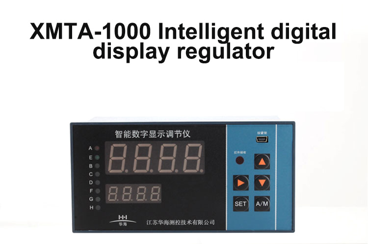
Display explain
1. Single row digital display: directly display the measured value of the instrument.
2. Double row digital display: the upper row displays the measured value. The lower row shows the set value. In the measurement state, the lower display can be switched to the percentage of the measured value by adding the key.
3. Double row nixie tube + single analog bar: the upper row displays the measured value. The lower row shows the percentage of the set value or the measured value, and a single analog bar indicates the percentage of the measured value or the percentage of the analog output.
4. Single row nixie tube + double row analog strip: the nixie tube displays the measured value of the instrument, and press the plus key to display the percentage of the measured value or the percentage of the analog output. The left analog bar indicates the percentage of the measured value; the right analog bar indicates the percentage of the set value or the percentage of the analog output.
5. Double row nixie tube + double row analog strip: the explanation of double row nixie tube is the same as that of (display description 2), and the explanation of double row analog strip is the same as that of (display description 4).
6. Indicator light: a light or j1light, which is SP1 alarm indicator light.
E lamp or J2 lamp is SP2 alarm indicator.
B lamp or J3 lamp is the SP3 alarm indicator.
C lamp or J4 lamp is SP4 alarm indicator.
The lamp or J5 lamp is SP5 alarm indicator.
Lamp or J6 lamp is SP6 alarm indicator.
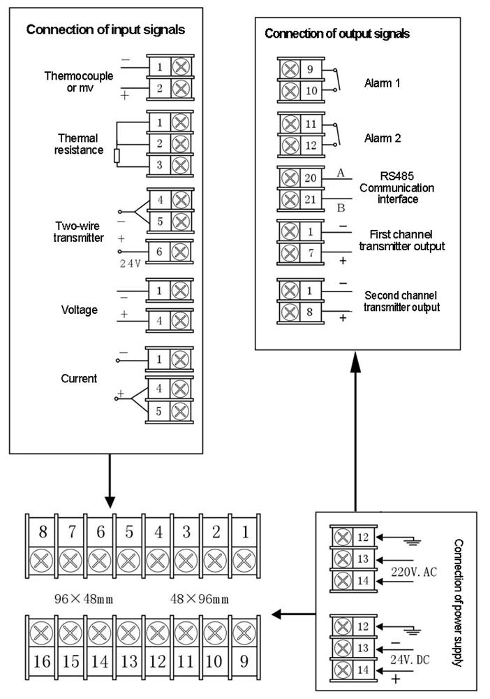
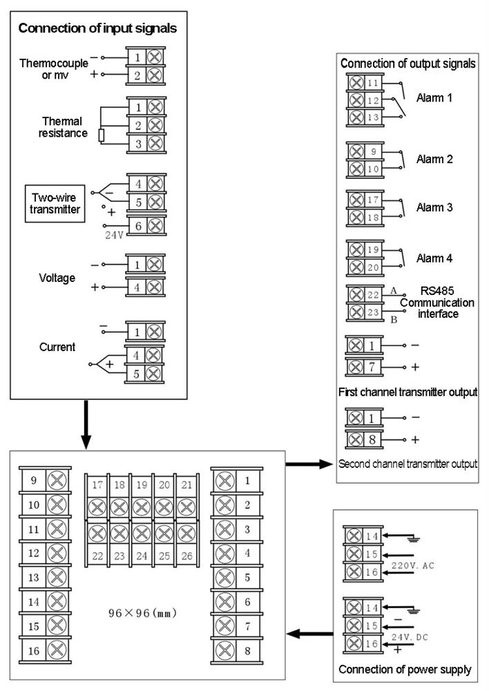
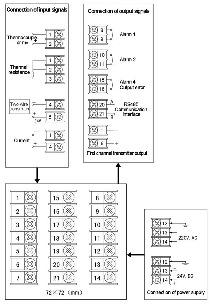
Instrument wiring
1.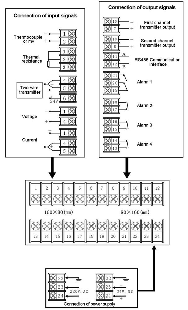 2.
2.
3.
4.