Product overview
The XMBA-7000 series intelligent dual input display regulator produced by our company adopts the special integrated circuit developed by ourselves and commissioned by Japanese integrated circuit manufacturers. It not only collects most functions of various regulating instruments in the current automatic control system, but also integrates the CPU, I / D interface, RS485 or RS232 communication interface, EPROM and D / a conversion and other circuits, supplemented by BOCAI This instrument has the following characteristics when used in the software system with numerous advantages, elaborate preparation and repeated debugging.
1. The instrument hardware is greatly reduced, the system structure is relatively simple, the process is significantly improved, there is no flying wire, no debugging potentiometer, all the parameter settings, the instrument calibration function selection are all completed by the software through the keyboard.
2. Four alarm outputs can be set, with more than ten alarm methods. It can be arbitrarily assigned to the main input or sub input, or to the difference between the main input and sub input, or to the sum value of the main input and sub input, or to the quotient value of the main input and sub input.
3. It can be set as one of the switching values to monitor the other three switching values selectively, so as to realize the intelligent acoustooptic alarm function with silencing time.
4. Two or three D / A output ports can be added optionally, which can be allocated to the main input or auxiliary input. The zero point and full degree value of analog output can be set arbitrarily in the displayed value range. The output can be photoelectrically isolated to provide 5V and 24 constant voltage source output.
5. Any complex control, adjustment, alarm, output and other functions can be operated simply by the instrument operator, with the set pressure protected by password, and then it can be used to become a fool instrument. The field operator will not be able to modify the locked parameters. There are four categories and hundreds of levels of anti-jamming modes set by the user, which can adapt to the interference sources of various environments.
Main performance
1. The input signal is thermocouple, thermal resistance and standard linear signal with double input and various graduation numbers, (the double input signal must be the same) or thermal resistance (PT100) and linear signal (please indicate when ordering).
2. The display process quantity exceeds the display range of any setting (- 1999-9999, 9999-1999, 0-3 decimal places) or 0-100%.
3. Triple display of dual input process quantity indication, dual analog bar indication, etc.
4. The display range of double input can be set separately.
5. The display values of main input and sub input can be added, subtracted and divided.
6. Control relay action after comparison between main input and auxiliary input.
7. State output after disconnection, disconnection and disconnection.
8. The state of the relay used for position control after disconnection, disconnection and disconnection has the function of holding.
9. Intelligent audible and visual alarm.
Product selection
| XMBA |
—— |
Instruction
|
|
Design No.
|
7 |
7000 series Double inputs instrument
|
|
Display
|
1 |
Single screen display
|
| 2 |
Double screens display
|
| 3 |
Single screen + single streamer
|
| 4 |
Single screen + double streamers
|
| 5 |
Double screens + single streamer
|
| 6 |
Double screens + double streamers
|
| 7 |
Triple screens display
|
| 8 |
Display as excavation plus small signal cutoff (Please remark ,when have order)
|
|
Input
|
1 |
The main and auxiliary inputs both are thermocouples (K、E、S、B、J、T、R、N)
|
| 2 |
The main and auxiliary inputs both are RTD (Pt100、Cu100、Cu50、BAz、BA、G)
|
| 3 |
The main and auxiliary inputs both are current or voltage(0~10mA、4~20mA、0~20mV、0~100mV、0~500mV、0~5V、1~5V)
|
| 4 |
Main input is Pt100,auxiliary input is current or voltage.(Please remark ,when have order)
|
|
Control output and regulation mode (Switch output)
|
0 |
No relay output
|
| 1 |
1 Relay (Any operation value assigned to main input or auxiliary input or between main and auxiliary input)
|
| 2 |
2 Relays (Any operation value assigned to main input or auxiliary input or between main and auxiliary input)
|
| 3 |
3 Relays (Any operation value assigned to main input or auxiliary input or between main and auxiliary input)
|
| 4 |
4 Relays (Any operation value assigned to main input or auxiliary input or between main and auxiliary input)
|
|
Additional functions
|
0 |
No additional functions
|
| 1 |
With status output after TC disconnection, RTD disconnection and wires disconnection
|
|
Dimension
|
H |
Horizontal 160×80
|
Portiforium 152×76
|
| V |
Vertical 80×160
|
Portiforium 76×152
|
| F |
Square 96×96
|
Portiforium 92×92
|
| Q |
Square 72×72
|
Portiforium 68×68
|
|
Output
|
A |
Main input or auxiliary input can be independently transmitted and
output
|
| B |
(Main input ± auxiliary input)×(Lup-Ldo)
|
| C |
(Main input ± auxiliary input)×(Lup-Ldo)+ Display displacement +PFS
|
| D |
Operation value output of main input and auxiliary input
|
| E |
The main input and the auxiliary input are independent transmitting of each other
|
| F |
Special request output
|
|
Output power 24V
|
P |
Without 24VDC output as default
|
|
With 24VDC output(2 Wires transmitter power option)
|
|
Communication
|
T |
No communication
|
|
With RS485 or RS232 communication
|
|
Power supply
|
K
W
|
220VAC
|
|
Switch power supply 85~260VAC
|
|
Switch power supply 18~36VDC or 18~36VAC
|
|
Technical indicators
1. Measurement accuracy: ± 0.5% FS ± 1D ± 0.2% FS ± 1D
2. Alarm mode: upper limit, lower limit, upper and lower limit, upper return difference, lower return difference, double return difference, OK mode, absolute value mode, etc
3. Transmission output accuracy: ± 0.2% FS
4. Analog output drive load impedance
Current signal: 0 ~ 10mA ≥ 1.5k Ω; 4 ~ 20mA ≥ 750 Ω
Voltage signal: 0-5V, 1-5V output impedance ≤ 1 Ω
5. Analog input impedance
Current signal: ≤ 50 Ω; voltage signal: ≥ 50K Ω
6. Relay contact capacity: AC220V, 3A (resistive load)
7. Parameter retention time set after power failure: ≥ 20 years
8. Insulation strength: AC voltage 1500V, 1 minute
9. Insulation impedance: above 50m Ω
10. Power supply: AC220V, 50Hz, ≤ 6W or 24V
11. Working environment requirements: temperature 0 ~ 50 ℃, relative humidity ≤ 85%, no corrosive gas, no vibration
Display description
1. Double screen display
Upper row (left row) nixie tube displays main input measurement signal
The lower row (right row) nixie tube displays the measurement signal of the auxiliary input, or displays the operation value between the main input and the auxiliary input
2. Double screen display + single analog bar
Upper row (left row) nixie tube displays main input measurement signal
The lower row (right row) nixie tube displays the measurement signal of the auxiliary input, or displays the operation value between the main input and the auxiliary input
The analog bar shows% of the process amount of the input signal, and the display switching between the main and auxiliary channels is realized with the minus key
3. Single screen display + dual-mode strip fitting
The nixie tube displays the main input measurement signal or the auxiliary input measurement signal
Display switching between main and auxiliary channels is realized by adding keys
The first 36 line analog bar shows the measurement signal of the main input in percentage form
The second 36 wire analog bar displays the measurement signal of sub input in percentage form
4. Double screen display + dual mode strip fitting
Upper row (left row) nixie tube displays main input measurement signal
The lower row (right row) nixie tube displays the sub input measurement signal or displays the operation value between the main input and the sub input
The left analog bar displays the measurement signal of the main input as a percentage
The right analog bar displays the measurement signal of the sub input as a percentage
5. Indicator light
A lamp or j1lamp, SP1 alarm indicator
E lamp or J2 lamp, SP2 alarm indicator
B light or J3 light, SP3 alarm indicator
C light or J4 light is SP4 alarm indicator light
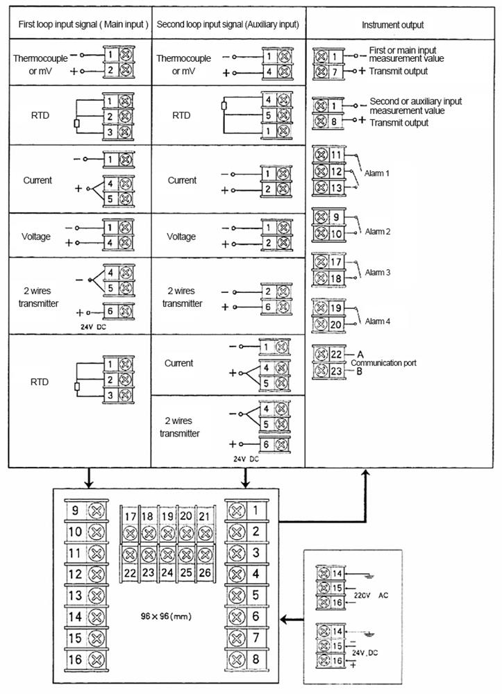
Rear panel and electrical wiring
1.
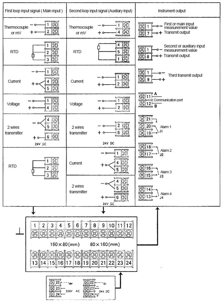 2.
2.