Working principle
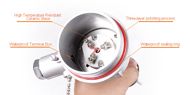
The structure and principle of explosion-proof thermal resistance and assembly thermal resistance are basically the same. The difference is that the junction box (shell) of explosion-proof products is designed with explosion-proof special structure. The junction box is made of high-strength aluminum alloy die-casting, and has enough internal space, wall thickness, mechanical strength, and thermal stability of rubber sealing ring in line with national explosion-proof standards. Therefore, when the junction box When the explosive gas mixture explodes, its internal pressure will not damage the junction box, and the resulting heat energy can not be diffused and propagated outwards.
As the product adopts the above explosion-proof special structure, the product completely conforms to the range of explosion-proof temperature level of D Ⅱ BT4 or D Ⅱ CT6. As long as the user strictly abides by the product use rules, the product can achieve reliable explosion-proof effect.
Technical indicators
★ Temperature measurement range and allowable error
|
Model
|
Graduation
|
Range
|
Accuracy class
|
Allowable error △t℃
|
WZP
WZP2
WZPK
WZPK2 |
Pt100 |
-200~500 |
Class A
|
±<650℃
±(0.15+0.002∣t∣) |
|
Class B
|
-200~800℃ Allowable error ±(0.30+0.005∣t∣
|
Note: "t" refers to the absolute value of the measured temperature of the temperature sensing element, and the double platinum resistors are only available for class B.
"*" Class A is special order
★ Nominal pressure
Generally, it refers to the static external pressure that the protection pipe can bear without breaking under normal temperature, and the test pressure is generally 1.5 times of the nominal pressure. In fact, the allowable nominal pressure is not only related to the material, diameter and wall thickness of the protection pipe, but also related to its structural form, installation method, insertion depth and the flow rate and type of the measured medium.
★ Insulation resistance of thermal resistance
The test voltage of insulation resistance at room temperature can be any value of DC 10-100v, the ambient temperature should be within the range of 15-35 ℃, and the relative temperature should not be more than 80%. The insulation resistance at room temperature shall not be less than 100m Ω.
★ Allowable current of thermal resistance
The maximum measured current through platinum resistance shall not exceed 5mA
★ Explosion proof type and class group
Explosion proof group: D Ⅱ BT4 or D Ⅱ cT4; D Ⅱ BT6 or D Ⅱ CT6
Enclosure protection grade: IP54
Explosion proof mark representation method of flameproof thermal resistance

★ Explosion proof grade
The explosion-proof grade of the flame-proof thermal resistance is divided into three grades A, B and C according to the maximum safety clearance applicable to explosive gas mixture.
★ Temperature group
According to the highest surface temperature of the exposed part, the temperature group of the flameproof thermal resistance is divided into six groups: T1-T6.
|
Temperature group
|
Allowable maximum surface temperature ℃
|
| T1 |
450 |
| T2 |
300 |
| T3 |
200 |
| T4 |
135 |
| T5 |
100 |
| T6 |
85 |
★ Please refer to the example table of flameproof thermocouple for combustible gas, steam level and temperature group of flameproof platinum resistance.
Types and specifications
|
Type
|
Model
|
Graduation
|
Range ℃
|
Diameter
|
Thermal response time τ0.5S
|
Nominal pressure MPa
|
Structure
|
Type
|
Ex class
|
| L |
Insertion/mm
|
|
RTD Pt10,Pt100
|
WZPK-24
WZPK2-24 |
Pt10
Pt100 |
-200~+500 |
Φ6
or
Φ5 |
≤12
≤8 |
10 |
Ex junction box , fixed thread installation M27×2
|
|
150
200
300
400
500
750
1000 |
d Ⅱ BT4
d Ⅱ BT6
or
d Ⅱ CT4
d Ⅱ CT6 |
WZPK-44
WZPK2-44 |
6.4 |
Ex junction box , fixed flange
|
Installation of fixtures
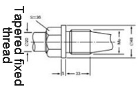
★ The installation of fixing device can be divided into three forms: fixed thread, tapered fixed thread and fixed flange. See the table for its structural dimension.
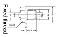 |
Protection tube diameter
|
M |
h |
S |
D0 |
Velocity
|
Maximum service pressure
|
Φ12
Φ16 |
M27×2 |
32 |
32 |
Φ40 |
|
10 |
 |
|
M33×2 |
33 |
36 |
Φ48 |
80 |
30 |
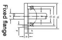 |
Φ12
Φ16 |
D2 |
D1 |
D0 |
d0 |
H |
h |
6.4 |
| Φ95 |
Φ65 |
Φ45 |
Φ14 |
Φ14 |
2 |
|
Type
|
Model
|
Graduation
|
Range ℃
|
Material
|
Thermal response time
τ0.5S
|
Nominal pressure MPa
|
Structure
|
Type
|
Ex class
|
| L |
Insertion /mm
|
|
RTD Pt10,Pt100
|
WZP-24SA |
Pt10
Pt100 |
-200~500 |
1Cr18Ni9Ti
or
0Cr18Ni
12Mo2T
|
≤90 |
10 |
Ex junction box , fixed thread installation M27×2
|
300
350
400
450
550
650
900
1150 |
150
200
250
300
400
500
750
1000 |
d Ⅱ BT4
d Ⅱ BT6
or
d Ⅱ CT4
d Ⅱ CT6 |
| WZP2-24SA |
| WZP-44SA |
| WZP2-44SA |
6.4 |
Ex junction box , fixed flange installation
|
WZP-64S
WZP2-64S |
1Cr18Ni9Ti |
30 |
Cone protection tube
M33×2
|
|
100
200
300 |