 |
 |
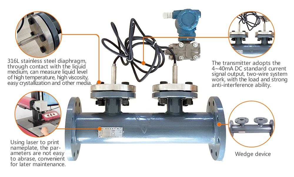
Product ·Structure diagram
Product Internal Structure|Decomposition Analysis|Just to give you a better understanding of the product
Committed to provide solution for field instruments
|
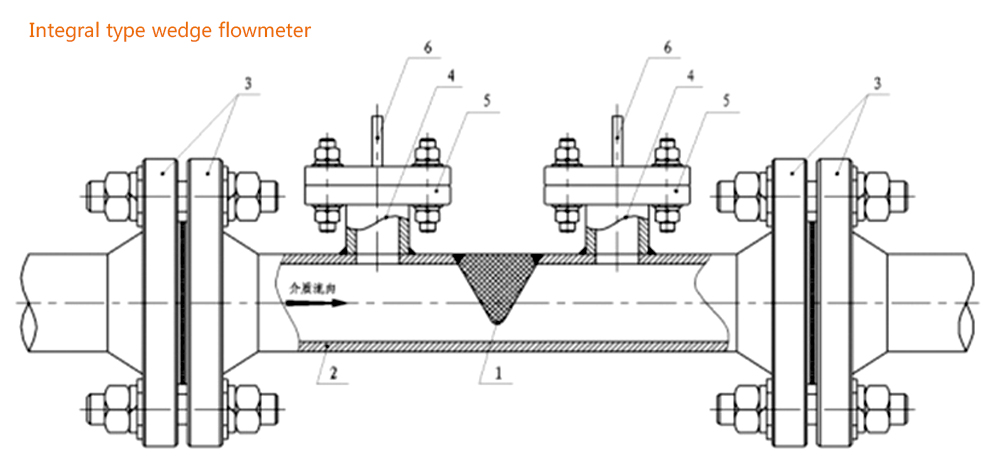 |
| 1. Wedge block;2. Measuring conduit;3. Connecting flange;4. Pressure tapping conduit; 5. Pressure tapping flange;6. Double flange diaphragm type differential pressure transmitter |
|
| |
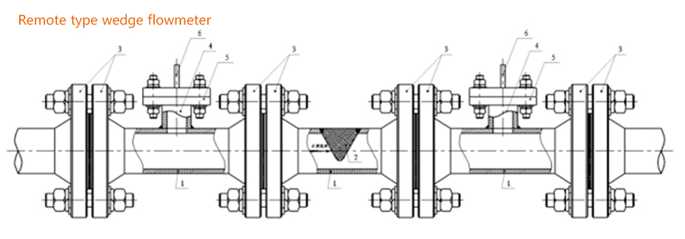 |
| 1. Measuring conduit;2. Wedge block;3. Connecting flange;4. Pressure tapping conduit; 5. Pressure tapping flange;6. Double flange diaphragm type differential pressure transmitter |
|
| |
 |
Product • parameters
Various parameters for you to choose|HUAHAI instrument Strive for excellence
Committed to provide solution for field instruments
|
| Product name |
Wedge flowmeter |
Applicable pipe diameter D |
15mm~300mm (More than DN300 can be made) |
| Uncertainty |
±1.0~1.5% FS(When leaving the factory, calibrate one by one) |
Repeatability |
0.2~0.5% |
| Range ratio |
10:1 |
Working pressure |
-0.1Mpa~6.4Mpa |
| Working temperature |
-50℃~400℃ |
Minimum flow velocity |
0.01m/s |
| Measuring liquid viscosity |
Upper limit 500mPa.S |
Reynolds number range |
Lower limit 300,upper limit more than 1*106 |
| Applicable medium |
Water, sewage, gas, steam, high viscosity liquid,solid-liquid mixed type |
|
 |
| Nominal diameter D |
L (mm) |
Nominal diameter D |
L (mm) |
Nominal diameter D |
L (mm) |
| DN15 |
400 |
DN65 |
450 |
DN150 |
600 |
| DN25 |
400 |
DN80 |
480 |
DN200 |
620 |
| DN40 |
400 |
DN100 |
520 |
DN250 |
650 |
| DN50 |
400 |
DN125 |
550 |
DN300 |
700 |
|
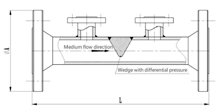 |
| Flange execution standard:JB/T81-1994、JB/T82.1-1994、JB/T82.2-1994(the picture above) |
|
 |
| Model |
Description |
| HLGX |
Wedge flowmeter |
| |
Code |
Classification by structure characteristics |
| |
Y |
Integral type wedge flowmeter |
| |
F |
Remote type wedge flowmeter |
| |
Code |
Nominal pressure(MPa) |
| |
1.6 |
1.6 |
| |
2.0 |
2.0 |
| |
2.5 |
2.5 |
| |
4.0 |
4.0 |
| |
6.4 |
6.4 |
| |
Code |
Caliber |
| |
15-300 |
DN15-DN300 |
| |
Code |
Medium |
| |
1 |
Liquid |
| |
2 |
Gas |
| |
3 |
Steam |
| |
Code |
Compensation form |
| |
N |
No pressure, temperature compensation |
| |
P |
With pressure compensation output |
| |
T |
With temperature compensation output |
| |
Code |
Transmitter differential pressure range |
| |
1 |
Medium differential pressure range |
| |
2 |
High differential pressure range |
| |
Code |
Whether with the field display |
| |
W |
Throttling device sensor |
| |
X |
Intelligent throttling device (flowmeter) |
|