 |
 |
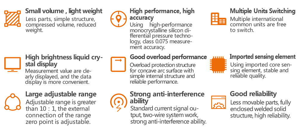
| The differential pressure transmitter Focp is suitable to measure liquid, gas, or steam flow as well as liquid level, density and pressure. 1001- B/C outputs a 4 to 20 mA DC HART signal corresponding to the measured differential pressure. Other key features include quick response, remote set-up using communications, self-diagnostics and optional status output for pressure high/low alarm. |
 |
The differential pressure transmitter includes two functional units:
—Main unit
—Auxiliary Unit
The main unit includes a sensor and process connection. The completely welded sensor module is a twin-chamber system with an integral overload diaphragm, a temperature sensor and the silicon differential pressure sensor. The temperature sensor as a temperature compensated reference value to compensate for the temperature drift. |
|
Standard·Specifications
HUAHAI instruments|Strive for excellence
Committed to provide solution for field instruments
|
 |
| Reference Accuracy of Calibrated Span (includes terminal-based linearity, hysteresis, and repeatability) |
| ± 0.075% |
| If TD>10 (TD=URL/SPAN): ±(0.0075×TD)% The square root accuracy is 1.5 times of reference accuracy of calibrated span. |
|
| Ambient Temperature Effects |
|
| Span Code |
-20℃~65℃ |
| A |
±(0.45×TD+0.25)%×Span |
| B |
±(0.30×TD+0.20)%×Span |
| C/D/E |
±(0.20×TD+0.10)%×Span |
| Span Code |
-40℃~-20℃ & 65℃~85℃ |
| A |
±(0.45×TD+0.25)%×Span |
| B |
±(0.30×TD+0.20)%×Span |
| C/D/E |
±(0.20×TD+0.10)%×Span |
|
|
|
| Span Code |
Static Pressure Effects |
| A |
±(0.15%URL+0.10%Span)/4MPa |
| B |
±(0.10%URL+0.075%Span)/16MP |
| C/D/E |
±(0.05%URL+0.05%Span)/16MPa |
|
|
|
|
| Span Code |
Overpressure Effects |
| A |
±0.2%×Span/4MPa |
| B |
±0.2%×Span/16MPa |
| C/D/E |
±0.1%×Span/16MPa |
|
|
|
| Span Code |
Stability |
| A |
±0.5%×Span/1year |
| B |
±0.2%×Span/1 year |
| C/D/E |
±0.1%×Span/1 year |
|
|
|
|
|
|
 |
|
|
| Span/ Range Limits |
kPa |
mbar |
| A |
Span |
0.1~1 |
1~10 |
| Range Limits |
-1~1 |
-10~10 |
| B |
Span |
0.2~6 |
2~60 |
| Range Limits |
-6~6 |
-60~60 |
| C |
Span |
0.4~40 |
4~400 |
| Range Limits |
-40~40 |
-400~400 |
| D |
Span |
2.5~250 |
25~2500 |
| Range Limits |
-250~250 |
-2500~2500 |
| E |
Span |
20~2000 |
0.2~20 bar |
| Range Limits |
-500~2000 |
-5~20bar |
|
|
|
| Zero can be fully elevated or suppressed, within the lower and upper range limits of the capsule. |
|
|
|
| External zero is continuously adjustable with 0.01% incremental resolution of span. Re-range can be done locally using the range setting switch. |
|
| Mounting Position Effects |
|
| Rotation in diaphragm plane has no effect. Tilting up to 90 degree will cause zero shift up to 0.4 kPa which can be corrected by the zero adjustment. |
|
|
|
| Two wire 4 to 20 mA DC output with digital communications, linear or square root programmable. HART FSK protocol is option superimposed on the 4 to 20 mA signal. Output range: 3.9 mA to 20.5 mA. |
|
| Failure Alarm (the mode can be selected) |
|
Low Mode (min): 3.7 mA
High Mode (max): 21 mA
No Mode (hold): Keep the effective value before the fault.
Note: The standard setting of failure alarm is High Mode. |
|
|
|
| The amplifier damping constant is 0.1 sec; The sensor damping constant is 0.1~1.6 sec, it depends on the range and range compression ratio. Amplifier damping time constant is adjustable from 0 to 60 sec by software and added to response time. |
|
|
|
| Ambient Temperature Limits |
|
-40 to 85°C
-20 to 65°C with LCD display or fluorine rubber sealing |
|
| Storage and Transportation Temperature Limits |
|
| -50 to 85°C; -40 to 85°C with LCD display |
|
| Working Pressure Limits (Silicone oil) |
|
| Maximum working pressure: 16MPa, 25MPa, 40MPa |
|
|
|
| 3.5kPa abs. to maximum working pressure. |
|
| One-way Overload Pressure Limit |
|
| The maximum one-way overload pressure is maximum working pressure. |
|
| Electromagnetic Compatibility (EMC) |
|
| Look the EMC Performance Table |
|
 |
| Supply & Load Requirements |
|
| 24 V DC supply, Maximum voltage limited: 42VDC, Minimum voltage limited: 12VDC, 15VDC(with LCD display) 230Ω to 600Ω for digital communication |
|
|
|
| The electrical connection is made via cable entry M20x1.5.The screw terminals are suitable for wire cross-sections up to 2.5mm2. |
|
|
|
| Flange with fixing thread 7/16-20 UNF and 1/4-18 NPT female thread on both sides. |
|
 |
| Sensor Body |
316L stainless steel |
| Isolating Diaphragm |
316L stainless steel/Hastelloy C |
| Nuts and Bolts |
304 stainless steel |
| Process Connector |
304 stainless steel |
| Fill fluid |
Silicone oil/Fluorinated oil |
| Process Connector Gasket |
Perbunan(NBR)/Viton(FKM)/Teflon(PTFE) |
| Amplifier Housing |
Aluminum with epoxy resin coat |
| Housing Gasket |
Perbunan(NBR) |
| Name plate and tag |
304 stainless steel |
| Weight |
3.3kg |
| Degrees of Protection |
IP67 |
|
|
|
| Items |
Test items |
Basic standards |
Test conditions |
Performance Level |
| 1 |
Radiated interference (Housing) |
GB/T 9254-2008 |
30MHz~1000MHz |
OK |
| 2 |
Conducted interference(DC power port) |
GB/T 9254-2008 |
0.15MHz~30MHz |
OK |
| 3 |
Electrostatic Discharge (ESD) Immunity |
GB/T 17626.2-2006 |
4kV(Line) 8kV(Air) |
B |
| 4 |
RF electromagnetic field immunity |
GB/T 17626.3-2006 |
10V/m (80MHz~1GHz) |
A |
| 5 |
Frequency magnetic field immunity |
GB/T 17626.8-2006 |
30A/m |
A |
| 6 |
Electrical Fast Transient Burst Immunity |
GB/T 17626.4-2008 |
2kV(5/50ns,5kHz) |
B |
| 7 |
Surge Immunity |
GB/T 17626.5-2008 |
1kV(line to line) 2kV(line to ground) (1.2us/50us) |
B |
| 8 |
Conducted interference immunity induced by RF field |
GB/T 17626.6-2008 |
3V (150KHz~80MHz) |
A |
|
Note:(1)Performance level A description: The technical specifications within the limits of normal performance.
(2)Performance level B description: Temporary reduction or loss of functionality or performance, it can restore itself. The actual operating conditions, storage, and data will not be changed. |
|
|
|
|
|
| Horizontal Impulse Piping Type(side face) |
Horizontal Impulse Piping Type(front side) |
|
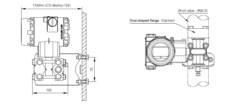 |
| Horizontal Impulse Wall mounting Type |
Vertical Impulse Piping Type |
|
 |
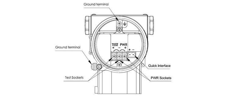 |
| Note:Quick interface functionally equivalent to the signal terminal |
|
 |
 |
 |
| Differential Pressure Transmitter |
| 10 |
Output |
| |
H
N |
4-20mA with HART
4-20mA |
| 20 |
Span |
| |
Gauge Pressure |
A
B
C
D
E |
0-100Pa~1kPa(0-10~100 mmH2O)/(0-1~10mbar)
0-200Pa~6kPa(0-20~600 mmH2O)/(0-2~60mbar)
0-400Pa~40kPa(0-40~4000 mmH2O)/(0-20~400mbar)
0-2.5kPa~250kPa(0-0.25~25 mH2O)/(0-25~2500mbar)
0-20kPa~2MPa(0-2~200 mH2O)/(0-0.2~20bar) |
| 30 |
Diaphragm fill fluid |
| |
A
C |
316L stainless steel Silicone oil
Hastelloy C Silicone oil |
| 40 |
Working pressure |
| |
1
2
3 |
16MPa
25MPa
40MPa |
| 50 |
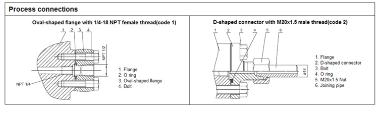
Process connections |
| |
N
B
U
D |
7/16-20 UNF and 1/4-18 NPT female thread, No relief valve
7/16-20 UNF and 1/4-18 NPT female thread, Relief valves at end of flanges
7/16-20 UNF and 1/4-18 NPT female thread, Relief valves at the upper part of the flange side
7/16-20 UNF and 1/4-18 NPT female thread, Relief valve at the lower part of the flange side |
| 60 |
Process connector gasket |
| |
N
F
P |
Perbunan(NBR)
Viton (FKM)
Teflon (PTFE) |
| 70 |
Special function |
| |
N
F
0 |
None
Square root output
Degrease cleansing treatment(Oxygen measurement must be with fluorinated oil filled capsule, Viton (FKM) gasket, <6MPa ,<60℃) |
| 80 |
Mounting bracket |
| |
N
1
2 |
None
304 stainless steel
Carbon steel galvanized |
| 90 |
Process connector accessory |
| |
N
1
2 |
None
Stainless steel oval-shaped flange with 1/2 NPT female thread
Stainless steel D-shaped connector with M20x1.5 male thread |
| 100 |
Integral indicator |
| |
N
1
2 |
None
LCD display
Backlit LCD display |
|